3 FILTER CIRCUITS
Filtering is done to eliminate unwanted content in audio, among other things. Differential filters that do the same job to differential signals as their single-ended cousins do to single-ended signals can be applied.
For differential filter implementations, the components are simply mirror imaged for each feedback loop. The components in the top feedback loop are designated A, and those in the bottom feedback loop are designated B. For clarity decoupling components are not shown in the following schematics. Proper operation of high-speed op-amps requires proper decoupling techniques. That does not mean a shotgun approach of using inexpensive 0.1-ìF capacitors. Decoupling component selection should be based on the frequencies that need to be rejected, and the characteristics of the capacitors used at those frequencies.
3.1 Single Pole Filters
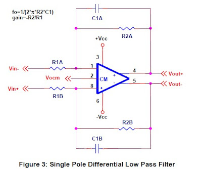
Single pole filters are the simplest filters to implement with single-ended op-amps, and the same holds true with fully-differential amplifiers. A low pass filter can be formed by placing a capacitor in the feedback loop of a gain stage, in a manner similar to single-ended op-amps:
A high pass filter can be formed by placing a capacitor in series with an inverting gain stage as shown in Figure 4:
A high pass filter can be formed by placing a capacitor in series with an inverting gain stage as shown in Figure 4:
Many double pole filter topologies incorporate positive and negative feedback, and therefore have no differential implementation. Others employ only negative feedback, but use the noninverting input for signal input, and also have no differential implementation. This limits the number of options for designers, because both feedback paths must return to an input.
The good news, however, is that there are topologies available to form differential low pass, high pass, bandpass, and notch filters. However, the designer might have to use an unfamiliar topology or more op-amps than would have been required for a single-ended circuit.
3.2.1 Multiple Feedback Filters
MFB filter topology is the simplest topology that will support fully-differential filters. Unfortunately, the MFB topology is a bit hard to work with, but component ratios are shown for common unity gain filters.
Reference 5 describes the MFB topology in detail.
Reference 5 describes the MFB topology in detail.
There is no reason why the feedback paths have to be identical. A bandpass filter can be formed by using nonsymmetrical feedback pathways (one low pass and one high pass). Figure 7 shows a bandpass filter that passes the range of human speech (300 Hz to 3 kHz).
3.2.2 Akerberg Mossberg Filter
Akerberg Mossberg filter topology is a double pole topology that is available in low pass, high pass, band pass, and notch. The single ended implementation of this filter topology has an additional op-amp to invert the output of the first op-amp. That inversion in inherent in the fullydifferential op-amp, and therefore is taken directly off the first stage. This reduces the total number of op-amps required to 2:
Biquad filter topology is a double pole topology that is available in low pass, high pass, band pass, and notch. The highpass and notch versions, however, require additional op-amps, and therefore this topology is not optimum for them. The single-ended implementation of this filter topology has an additional op-amp to invert the output of the first op-amp. That inversion is inherent in the fully-differential op-amp, and therefore is taken directly off the first stage. This reduces the total number of op-amps required to 2:
Hernández Caballero Indiana
Asignatura: CAF
Fuente: http://focus.ti.com/lit/an/sloa064/sloa064.pdf


No hay comentarios:
Publicar un comentario